
Magnetometer: How It Works, Types, Uses, and Calibration

A magnetometer is an instrument that measures the strength, direction, or variation of a magnetic field. These sensors range from miniature components inside smartphones to highly sensitive systems used in laboratories, geological surveys, spacecraft, and medical research. Although all magnetometers detect magnetic effects, they do not operate in the same way or provide the same type of measurement.
Some report total field strength, while others measure directional components along multiple axes. This guide explains the physical principles behind magnetometers, the main laboratory and survey technologies, the specifications used to compare them, calibration methods, and their most important applications in science, industry, navigation, exploration, and everyday electronic devices.
Table of Contents:
What Is a Magnetometer?
A magnetometer is an instrument that detects and measures magnetic fields. Depending on its design, it may measure only the total strength of a field or also determine its direction and individual spatial components. Magnetometers range from compact sensors inside smartphones to highly sensitive laboratory systems used to study materials, the human brain, and magnetic phenomena in space.
Magnetic Fields and Measurement Units
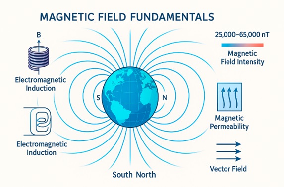
A magnetic field is the region around a magnet, electric current, or magnetized material where magnetic forces can act. Because a magnetic field has both magnitude and direction, it is described as a vector field.
Magnetic flux refers to the total magnetic field passing through a defined surface. Magnetic flux density describes how concentrated that field is at a particular location and is the quantity most magnetometers measure.
The standard SI unit of magnetic flux density is the tesla (T). Because one tesla is a relatively strong field, practical measurements often use smaller units such as the microtesla (µT), equal to one millionth of a tesla, and the nanotesla (nT), equal to one billionth of a tesla. Earth’s surface magnetic field is typically measured in tens of microteslas. The gauss (G), a non-SI unit still used in some industries, equals 0.0001 tesla.
What Does a Magnetometer Measure?
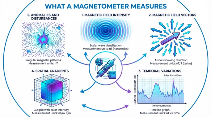
A magnetometer can measure several characteristics of a magnetic field:
- Field strength: the magnitude of the magnetic field at a specific point.
- Direction: the orientation of the field, often expressed relative to geographic or instrument axes.
- Vector components: the field values along the X, Y, and Z axes.
- Temporal changes: variations in magnetic intensity or direction over seconds, hours, or longer periods.
- Spatial gradients: differences in the field between nearby positions.
- Magnetic anomalies: local departures from an expected background field, often caused by rocks, buried objects, structures, or electrical equipment.
Not every magnetometer measures all these properties. Its output depends on the sensing technology, number of axes, calibration, and intended application.
Types of Magnetometer at a Glance
Magnetometers can first be grouped by where and how they are used. Laboratory magnetometers examine samples or controlled magnetic phenomena, often under carefully regulated temperature, field, or vacuum conditions. Survey magnetometers are designed for measurements in the field, including geological exploration, archaeology, navigation, and magnetic mapping.
They are also classified as scalar or vector instruments. A scalar magnetometer measures the total magnitude of the field without reporting its direction. A vector magnetometer measures directional components, allowing the field’s orientation to be calculated. Three-axis magnetometers, common in electronic devices and navigation systems, record the field along three perpendicular axes.
Performance and Capabilities
Several specifications determine whether a magnetometer is suitable for a particular task. Sensitivity describes how strongly the instrument responds to a small field change. Resolution is the smallest change it can distinguish in its output, while accuracy indicates how closely a reading represents the true value.
The measurement range defines the weakest and strongest fields the sensor can measure without losing useful performance. Sampling rate indicates how many readings it can produce per second. Noise consists of unwanted fluctuations that can obscure weak signals. Dynamic range describes the span between the smallest detectable signal and the largest measurable field. These characteristics must be considered together; an instrument with excellent sensitivity may not be the best choice if it has limited range, slow sampling, or demanding operating conditions.
Magnetometer vs. Gaussmeter vs. Teslameter
The terms magnetometer, gaussmeter, and teslameter often overlap. Magnetometer is the broadest term for an instrument that measures magnetic fields. Gaussmeter and teslameter usually describe instruments that display magnetic flux density in gauss or teslas.
In practice, gaussmeters and teslameters are commonly associated with industrial, engineering, and laboratory measurements, particularly when checking magnets, motors, electronic components, or magnetic materials. The name alone does not define a completely different operating principle; the distinction often reflects the unit displayed, measurement range, or professional context.
Early Magnetometers and Their Development
Early magnetic instruments relied on suspended magnetic needles to compare field direction and relative strength. In the 1830s, Carl Friedrich Gauss helped establish methods for absolute magnetic measurement, making it possible to quantify Earth’s magnetic field more reliably.
During the twentieth century, fluxgate technology made magnetometers more sensitive, rugged, and suitable for mobile use. Fluxgate instruments became important in geophysical surveying, military detection, aircraft systems, and later spacecraft research. Advances in electronics and microfabrication eventually reduced magnetometers from specialized instruments to miniature sensors used in phones, vehicles, drones, industrial equipment, and portable scientific systems.
How Does a Magnetometer Work?
A magnetometer works by detecting how a magnetic field affects a sensing element and converting that interaction into a measurable signal. The sensing element may be a coil, semiconductor, magnetic core, atomic vapor, proton-rich liquid, or superconducting circuit. Electronics then amplify, filter, and process the signal before presenting the result as magnetic field strength, directional components, or both.
The exact conversion method depends on the magnetometer technology, but the general sequence is similar: the magnetic field interacts with the sensor, the sensor produces a physical response, and the instrument translates that response into a calibrated magnetic measurement.
From Magnetic Field to Electrical Signal
Different magnetometers convert magnetic effects into different types of output. Some generate a voltage when the field changes or when electrical current passes through a semiconductor. Others detect changes in electrical current, oscillation frequency, light absorption, or magnetic flux.
The raw signal is usually too weak or noisy to use directly. Signal-conditioning circuits amplify it, remove unwanted frequencies, compensate for known sensor errors, and convert analog signals into digital data. Calibration factors are then applied so that the output corresponds to a recognized magnetic unit, such as teslas, microteslas, gauss, or nanoteslas.
Environmental conditions can affect this process. Temperature changes, nearby metal, electrical currents, mechanical vibration, and the orientation of the sensor may alter the reading. For this reason, many magnetometer systems include temperature compensation, filtering, and calibration procedures.
Scalar and Vector Measurements
A scalar magnetometer produces a single value representing the total magnitude of the magnetic field. Because it does not measure direction, its result is generally less dependent on the instrument’s orientation. This makes scalar instruments useful for magnetic surveys in which changes in total field strength are the primary interest.
A vector magnetometer measures the field along one or more defined directions. A three-axis sensor records perpendicular X, Y, and Z components. These values can be combined to calculate total field magnitude, while their relative values reveal the field’s direction with respect to the sensor.
Directional measurements require accurate axis alignment and orientation data. In navigation systems, magnetometer readings are therefore often combined with accelerometers and gyroscopes to determine heading and compensate for device movement or tilt.
Main Magnetometer Operating Principles
Several physical effects can be used to detect magnetic fields:
- Electromagnetic induction: a changing magnetic flux produces a voltage in a coil.
- Hall effect: a magnetic field creates a transverse voltage across a current-carrying semiconductor.
- Magnetic saturation: an external field changes how a ferromagnetic core responds as it is repeatedly driven into saturation.
- Nuclear precession: atomic nuclei rotate, or precess, at a frequency related to the surrounding magnetic field.
- Optical pumping: light prepares atomic energy states whose behavior changes in the presence of a magnetic field.
- Quantum interference: superconducting circuits detect extremely small changes in magnetic flux through quantum effects.
Each principle offers a different balance of sensitivity, speed, range, portability, and operating complexity.
Laboratory Magnetometers
Laboratory magnetometers characterize magnetic materials and controlled magnetic phenomena. Unlike survey instruments that map fields across an area, they usually measure how a sample responds while the applied field, temperature, orientation, frequency, or pressure is varied.
They can determine magnetic moment, magnetization, coercivity, remanence, susceptibility, and hysteresis. A hysteresis loop shows how a material’s magnetization changes as the applied field is increased, reversed, and returned, helping identify properties relevant to permanent magnets, soft magnetic materials, superconductors, and other systems.
SQUID Magnetometers
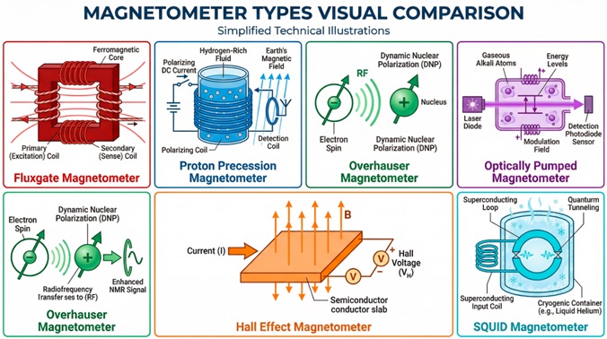
A SQUID magnetometer uses a superconducting quantum interference device to detect extremely small changes in magnetic flux. Its sensor contains a superconducting loop interrupted by one or more Josephson junctions, thin barriers through which paired electrons can tunnel. Changes in flux alter the loop’s electrical behavior and produce a measurable signal.
In a common laboratory configuration, the sample moves through detection coils coupled to the SQUID. The signal is used to calculate magnetic moment while researchers vary temperature or apply an external field. This allows the study of weak magnetism, phase transitions, superconductivity, and nanoscale magnetic materials.
SQUID systems require cryogenic cooling so their sensing components remain superconducting. Traditional instruments use liquid helium, while some modern systems use closed-cycle cryocoolers. Their sensitivity and flexibility make them important in condensed-matter physics, materials science, geology, and biomagnetism. SQUID arrays are also used in magnetoencephalography to detect weak magnetic fields generated by neural activity.
Inductive Pickup Coils and Pulsed-Field Magnetometry
An inductive pickup coil measures changing magnetic flux. When the flux through the coil changes, it generates a voltage. In laboratory systems, pickup coils may detect the response of a moving sample or record rapid changes during a magnetic-field pulse.
Pulsed-field magnetometry produces a strong field for a brief interval rather than maintaining it continuously. The sample signal must be separated from the much larger voltage caused by the changing applied field, often through compensated coils, background subtraction, and signal integration.
These systems allow researchers to investigate materials at fields that may be difficult to generate continuously. They are used to examine magnetic phase transitions, saturation, and other high-field behavior, although short measurement times, heating, vibration, and complex signal processing can make the experiments demanding.
Vibrating-Sample Magnetometers
A vibrating-sample magnetometer, or VSM, measures magnetic moment by moving a sample periodically within a magnetic field. The sample is mounted on a rod and vibrated near pickup coils. As the magnetized sample moves, the magnetic flux through the coils changes and induces an alternating voltage.
When the vibration geometry and calibration are known, the voltage amplitude is proportional to the sample’s magnetic moment. By sweeping the applied field, a VSM can record a hysteresis loop and determine saturation magnetization, remanence, coercive field, and related properties. Measurements can also be repeated at different temperatures or sample orientations.
VSM systems provide relatively fast measurements and accommodate thin films, powders, nanoparticles, alloys, permanent magnets, and other sample forms. They are generally less sensitive than SQUID systems but are often easier to operate and well suited to routine material characterization.
Torque, Faraday Force, and Alternating-Gradient Magnetometry
Torque magnetometry measures the rotational force on a magnetic sample when its magnetic moment is not aligned with the applied field. It is especially useful for studying magnetic anisotropy, meaning the dependence of magnetic behavior on direction, as well as crystal orientation and directional electronic properties.
Faraday force magnetometry places a sample in a magnetic-field gradient. The sample experiences a force related to its magnetization and the gradient, and a sensitive balance or force sensor measures that force.
Alternating-gradient magnetometry applies a small oscillating field gradient that produces a periodic force on the sample. Detecting the resulting motion provides a fast and sensitive measurement of magnetic moment. These force-based techniques require careful control of geometry, vibration, background forces, and calibration.
Optical Magnetometry and AC Susceptometry
Optical magnetometry measures magnetic behavior through changes in light, including polarization rotation, absorption, fluorescence, or shifts in atomic or electronic energy levels. It can provide high sensitivity without direct electrical contact and may be used to study atomic vapors, thin films, microscopic regions, or magnetic dynamics.
AC susceptometry applies a small alternating magnetic field and measures the sample’s time-dependent response. Magnetic susceptibility describes how readily a material becomes magnetized. The response is often separated into an in-phase component, associated with reversible magnetization, and an out-of-phase component, associated with energy loss or delayed behavior.
By varying frequency, temperature, and field amplitude, AC susceptometry can reveal magnetic relaxation, nanoparticle blocking, superconducting transitions, and spin-glass behavior. It is most useful when the timing and energy dissipation of the magnetic response matter as much as its overall strength.
Survey Magnetometers
Survey magnetometers measure magnetic fields outside controlled laboratory conditions. They are carried by field crews or mounted on vehicles, aircraft, ships, drones, satellites, and fixed observatories. Their measurements support geological mapping, mineral exploration, archaeology, navigation, environmental investigations, and studies of Earth’s magnetic field.
A field instrument must remain stable while temperature, motion, orientation, vibration, and nearby magnetic materials change. The best design depends on whether a survey requires total-field measurements, directional information, rapid sampling, or detection of small local anomalies.
Scalar Magnetometers
Scalar magnetometers measure the total magnitude of the magnetic field and report one value at each observation point. Because the result does not describe direction, it is generally less sensitive to sensor orientation than a vector measurement. Total-field instruments are widely used in ground, marine, and airborne surveys to identify intensity changes caused by geology or buried magnetic material.
A proton precession magnetometer contains a hydrogen-rich liquid. A temporary magnetic field aligns the hydrogen nuclei, or protons. After that field is removed, the protons precess around the ambient field at a frequency proportional to its strength. These instruments provide absolute total-field measurements and have long been used in geophysics and magnetic observatories. Their limitations include relatively slow cycling and reduced performance where the field changes sharply across the sensor volume.
An Overhauser magnetometer also measures proton precession, but it uses the Overhauser effect to transfer polarization from electrons to protons. This strengthens the signal while requiring less polarization power than a conventional proton system. Overhauser instruments can offer faster sampling and lower power consumption, making them useful for walking surveys, base stations, and continuous recording.
Cesium vapor and potassium vapor magnetometers are optically pumped atomic instruments. Light prepares the atoms in selected energy states, and the magnetic field changes their resonance behavior. The resulting frequency provides an absolute measure of total field strength. Their rapid response and high sensitivity make them useful in detailed aeromagnetic, marine, archaeological, and unexploded-ordnance surveys. However, instrument orientation can create angular regions of reduced response called dead zones.
A metastable helium-4 magnetometer uses optically prepared helium atoms and magnetic resonance to determine field strength. Helium systems have been used in airborne and space measurements because they can combine high sensitivity with rapid sampling. Some advanced helium instruments can also derive vector information, although scalar measurement remains an important mode.
Vector Magnetometers
Vector magnetometers measure directional components of a magnetic field. A three-axis instrument records the field along three perpendicular axes, allowing researchers to determine its magnitude and orientation. These measurements are essential in navigation, geomagnetic observatories, spacecraft, and surveys where directional changes provide useful information.
The fluxgate magnetometer is one of the most established vector instruments. It drives a ferromagnetic core through repeated cycles of magnetic saturation and detects how an external field changes the symmetry of the response. Three orthogonal sensors can measure the complete field vector. Fluxgates operate continuously and cover static and slowly changing fields, although they require calibration for offset, scale, axis alignment, and temperature effects.
A Hall effect magnetometer measures the transverse voltage produced when current flows through a conductor or semiconductor in a magnetic field. Hall sensors are compact, inexpensive, and suitable for relatively strong fields, position sensing, and embedded systems. Their resolution and long-term stability are usually less suitable for weak geophysical anomalies than those of specialized survey instruments.
Magnetoresistive magnetometers use materials whose electrical resistance changes with magnetic field. Anisotropic, giant, and tunneling magnetoresistive sensors offer different combinations of sensitivity, size, power use, and range. They are common in electronic compasses, vehicles, drones, and compact platforms, but temperature drift, hysteresis, and nearby magnetic components must be controlled.
A rotating-coil magnetometer measures changes in magnetic flux as a coil rotates. It is useful for mapping the strength, direction, and field quality of accelerator and industrial magnets. Although it is a vector method, it is uncommon in mobile geological surveys because it depends on precise mechanical motion and geometry.
SQUID magnetometers can be configured as field sensors or gradiometers for extremely weak signals. Their exceptional sensitivity is useful in specialized geophysical and archaeological work, but cryogenic requirements and operational complexity limit routine field deployment.
Optically pumped magnetometers may operate as scalar or vector sensors depending on their configuration. They can provide high sensitivity without superconducting cooling and are increasingly used where compact size, low power, or rapid measurement is important. Performance may still depend on orientation, laser stability, and control of surrounding magnetic interference.
Gradiometers and Magnetic Survey Configurations
A magnetic gradiometer measures how the field changes over a known distance rather than reporting only its absolute value. A common configuration uses two synchronized magnetometers separated vertically or horizontally. Subtracting their readings and dividing by the sensor spacing produces an estimate of the magnetic gradient.
Because regional variations and distant disturbances affect both sensors similarly, differencing can suppress some common background signals while emphasizing nearby sources. Gradiometers are therefore effective for locating shallow archaeological features, pipelines, drums, unexploded ordnance, and other compact magnetic targets.
Survey systems may place sensors on a rigid frame, at aircraft wingtips, along a boom, or one above another. GPS provides positioning, while an inertial measurement unit may record roll, pitch, and heading. These data help correct for sensor orientation, platform motion, timing offsets, and the magnetic influence of the vehicle.
The usefulness of a gradient measurement depends on precise sensor spacing, synchronization, alignment, and calibration. When these factors are controlled, multi-sensor configurations can distinguish small local anomalies that might be difficult to separate from the much larger background field.
Magnetometer Types and Performance Comparison
No single magnetometer is best for every task. Performance depends on the field strength being measured, whether directional information is required, the speed of the measurement, environmental conditions, and the acceptable level of cost and complexity.
Key Specifications to Compare
The first distinction is whether the instrument produces a scalar total-field value or a vector measurement with directional components. Sensitivity indicates how effectively the sensor responds to weak fields, while resolution describes the smallest change visible in its output. Accuracy depends on calibration, stability, alignment, and environmental interference.
Measurement range and sampling rate are equally important. A sensor optimized for very weak fields may saturate near strong magnets, while a high-speed instrument may generate more noise or consume more power. Portability, temperature stability, cryogenic requirements, and relative cost can determine whether a technology is practical outside a laboratory.
| Type | Scalar or Vector | Typical Sensitivity | Main Advantage | Main Limitation | Common Applications |
|---|---|---|---|---|---|
| Proton precession | Scalar | About 0.1–1 nT | Absolute total-field measurement | Relatively slow sampling | Geological and archaeological surveys |
| Overhauser | Scalar | About 0.01–0.1 nT | Low power and faster readings | More complex than basic proton systems | Field surveys and base stations |
| Optically pumped atomic | Scalar or vector | Sub-nT to pT-level, depending on design | High sensitivity and rapid response | Orientation and optical-system requirements | Airborne surveys, research, space |
| Fluxgate | Vector | Approximately 0.01–1 nT | Continuous three-axis measurement | Offset and temperature drift | Spacecraft, observatories, navigation |
| Magnetoresistive | Vector | nT to µT-level | Compact and power efficient | Hysteresis and temperature effects | Drones, vehicles, electronic compasses |
| Hall effect | Vector | Usually µT-level | Low cost and wide measurement range | Lower weak-field sensitivity | Industrial systems and electronics |
| Vibrating-sample magnetometer | Sample measurement | High, configuration dependent | Fast material characterization | Requires controlled laboratory setup | Magnetic materials and thin films |
| SQUID | Scalar or vector | fT to pT-level in specialized systems | Exceptional sensitivity | Cryogenic cooling and high cost | Neuroscience and advanced research |
Sensitivity values are representative rather than universal because sensor geometry, bandwidth, shielding, and operating conditions can change performance substantially.
Which Magnetometer Is Best for Each Application?
For geological surveys, proton precession and Overhauser instruments provide reliable total-field measurements, while optically pumped systems are preferred when faster sampling or greater sensitivity is required. Archaeological surveys often use fluxgate gradiometers because they can detect shallow, localized anomalies efficiently.
Smartphones and embedded systems generally use Hall effect or magnetoresistive sensors because they are small, inexpensive, and energy efficient. Spacecraft commonly rely on fluxgate magnetometers for stable vector measurements, although atomic and SQUID-based systems may be used for specialized missions.
A VSM is a practical choice for routine laboratory analysis of magnetic materials, while SQUID magnetometers are selected when extremely weak magnetic moments must be measured. Neuroscience applications use SQUID or optically pumped sensors to detect biomagnetic signals. Industrial measurements typically favor Hall effect, magnetoresistive, or rotating-coil instruments, depending on field strength, required precision, and installation constraints.
How to Calibrate a Magnetometer
Magnetometer calibration identifies and corrects systematic errors between the magnetic field acting on a sensor and the values reported by the instrument. The procedure depends on the sensor technology and application. Calibrating a three-axis electronic compass, for example, requires different methods from calibrating a proton precession instrument or a laboratory SQUID system.
Why Magnetometer Calibration Matters
An uncalibrated magnetometer may report an incorrect field magnitude, direction, or both. A constant sensor bias can shift every reading, while unequal sensitivity between axes can distort the calculated field vector. Misaligned sensing axes introduce directional errors, and temperature changes may alter offsets or gain over time.
Nearby electrical currents, permanent magnets, steel structures, batteries, motors, and electronic components can also affect measurements. In navigation systems, these errors can produce an incorrect heading. In scientific surveys, they may create false anomalies or conceal weak magnetic signals.
Hard-Iron and Soft-Iron Distortion
Hard-iron distortion is caused by magnetic fields that remain approximately fixed relative to the sensor. Permanent magnets, magnetized screws, speakers, and direct electrical currents can create this effect. In three-axis data, hard-iron interference usually appears as an offset that shifts the center of the measurement distribution away from zero.
Soft-iron distortion occurs when ferromagnetic materials redirect or reshape the surrounding field. Vehicle frames, equipment housings, structural steel, and nearby components may amplify the field along one direction while reducing it along another. Instead of producing a simple offset, soft-iron effects distort the expected spherical distribution of rotated measurements into an ellipsoid.
Both forms of distortion are common in smartphones, drones, aircraft, vehicles, and compact instruments in which the sensor operates close to other components.
Three-Axis Magnetometer Calibration
A common calibration method rotates the sensor through many orientations so that it samples the surrounding field from multiple directions. Offset correction estimates and removes constant bias from each axis. Scale-factor correction compensates when the X, Y, and Z channels respond by different amounts to the same field.
Axis-alignment correction accounts for sensing axes that are not perfectly perpendicular or aligned with the instrument frame. Ellipsoid fitting combines these corrections mathematically by transforming distorted three-dimensional measurements into a sphere centered around the expected field magnitude.
Temperature compensation may require measurements at several operating temperatures. The instrument can then apply stored coefficients or a fitted model to correct predictable thermal changes in offset and sensitivity.
Field Calibration and Validation
Field calibration should be performed away from vehicles, reinforced concrete, power cables, tools, and other magnetic interference whenever possible. The instrument may be rotated in controlled orientations, exposed to known reference fields, or compared with a calibrated reference magnetometer.
Repeated measurements help reveal drift, noise, and orientation-dependent errors. After correction, validation should use data that were not part of the original calibration set. Survey instruments may also require checks of sensor spacing, platform magnetism, timing, and heading effects.
No single procedure applies to every magnetometer. Calibration must match the sensing principle, required accuracy, operating environment, and type of measurement being performed.
What Are Magnetometers Used For?
Magnetometers are used wherever magnetic fields reveal information that cannot be obtained easily through direct observation. Depending on the instrument and platform, they can map variations in Earth’s field, determine heading, characterize equipment, monitor space environments, or detect the weak fields produced by the human body.
Geophysics, Mineral Exploration, and Oil Exploration
In geophysics, magnetometers measure local variations caused mainly by differences in the magnetic properties of rocks. These anomalies help map faults, volcanic bodies, sedimentary basins, and magnetic formations beneath soil, water, or vegetation.
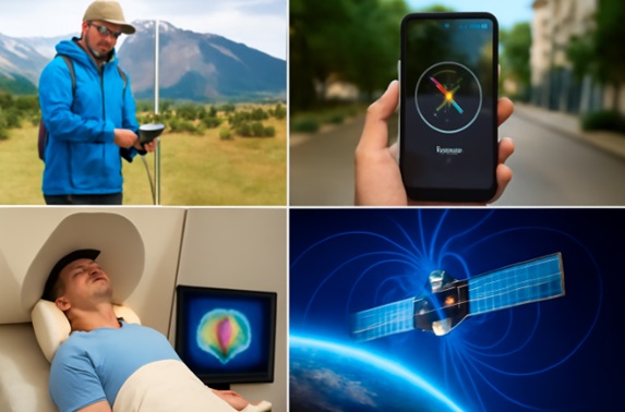
Mineral exploration surveys can identify structures associated with iron-rich rocks and deposits containing magnetic minerals. Measurements may be collected on foot or from vehicles, aircraft, drones, and ships. Magnetic data do not confirm that an economically valuable deposit is present, but they help narrow the areas requiring geological sampling or additional geophysical methods.
In coal, petroleum, and natural-gas exploration, magnetometers generally map basement geology, faults, intrusions, and basin structure rather than detect hydrocarbons directly. These interpretations complement seismic, gravity, and well data.
Archaeology
Archaeological magnetometry maps subtle changes produced by buried features without excavating them first. Ditches, pits, graves, walls, and filled trenches may create contrasts between disturbed soil and the surrounding ground. Kilns, hearths, fired bricks, and burned areas can produce stronger anomalies because heating may alter their magnetic properties.
Surveyors record closely spaced measurements across a grid and convert them into an image of magnetic variation. The map helps archaeologists examine site layouts and select excavation locations with minimal disturbance. Results depend on soil conditions and may be obscured by fences, pipes, modern debris, and electrical equipment.
Navigation, Aircraft, Drones, and Smartphones
A vector magnetometer can act as an electronic compass by comparing the measured field with the instrument’s axes. In an attitude and heading reference system, or AHRS, its data are combined with accelerometer and gyroscope measurements to estimate heading and orientation.
Aircraft and drones may use remote-mounted magnetometers to reduce interference from motors, wiring, batteries, and structural components. Calibration is essential because magnetic material on the platform can introduce heading errors.
Smartphones use miniature three-axis sensors for compass functions, map orientation, augmented-reality alignment, and applications that respond to device direction. Because a phone may be tilted or moving, its operating system combines magnetometer data with other motion sensors.
Military and Submarine Detection
Military systems use magnetometers for navigation, mapping, object detection, and magnetic anomaly detection. A large ferromagnetic object, including a steel vessel, can distort the surrounding geomagnetic field. Aircraft or marine sensors may detect that disturbance when the target is sufficiently close and the signal can be separated from background variation and platform noise.
Magnetometers can also support naval surveys and the detection of mines or unexploded ordnance. Effectiveness depends on target size, distance, orientation, sensor sensitivity, geology, and environmental interference.
Spacecraft, Auroras, and Space Weather
Spacecraft magnetometers measure planetary fields, magnetospheres, the solar wind, and interplanetary magnetic fields. Their observations show how charged particles and fields interact around Earth and other planets. Sensors are often installed on booms to reduce contamination from spacecraft electronics and magnetic components.
These measurements help scientists study magnetic reconnection, radiation environments, and space weather. They also contribute to research on auroras, which form when energetic particles enter the upper atmosphere through interactions involving the solar wind and Earth’s magnetosphere. Some spacecraft use field measurements as part of attitude determination or control.
Industrial and Scientific Applications
In accelerator physics, rotating coils, Hall probes, and other magnetometers map magnets that steer and focus particle beams. Industrial systems use magnetic sensors for position, speed, proximity, current, and rotation measurements in motors, robotics, manufacturing equipment, and vehicles.
Magnetometers also test permanent magnets, electromagnetic assemblies, shielding, and magnetic materials. Measurements may reveal changes associated with stress, fatigue, or defects in ferromagnetic components, although interpretation requires controlled conditions.
Medicine and Neuroscience
The electrical activity of nerves, muscles, the heart, and the brain produces weak magnetic fields. Magnetoencephalography, or MEG, measures fields generated by neuronal currents to study brain function and localize activity with high temporal resolution.
Conventional MEG systems use cryogenically cooled SQUID sensors. Newer systems may use optically pumped magnetometers that operate without superconducting cooling and can be positioned closer to the scalp. Biomagnetic measurements require shielding or active noise suppression because environmental fields are much stronger than signals from the body.
Magnetic Surveys and Data Interpretation
A magnetic survey becomes useful only when each reading is linked accurately to position, time, altitude, and sensor orientation. GPS and inertial data help locate measurements and correct for movement. Aircraft and vehicle surveys also require compensation for platform magnetism and heading-dependent errors.
Base-station data can help remove temporal changes in Earth’s field. Gradiometers emphasize nearby sources by measuring differences between separated sensors. After quality control, measurements may be corrected, leveled, filtered, interpolated into grids, and displayed as magnetic maps.
Processing can enhance boundaries, gradients, and anomaly patterns, but it does not eliminate geological ambiguity. Reliable interpretation combines magnetic images with geology, topography, other geophysical data, and knowledge of the survey conditions.
Frequently Asked Questions About Magnetometers
How Accurate Are Magnetometers?
Accuracy varies widely by technology and application. It depends on measurement range, calibration quality, sensor noise, temperature stability, alignment, and nearby interference. A laboratory instrument may measure extremely weak fields, while a smartphone sensor is designed mainly for orientation rather than precision scientific measurements.
Do Magnetometers Work Underwater?
Yes. Magnetic fields pass through water, so magnetometers can operate underwater when properly designed and sealed. Marine instruments may be towed behind ships, mounted on remotely operated vehicles, or installed on underwater platforms. Readings can be affected by the vessel, cables, motors, pressure-resistant housings, and nearby metal.
What Does a Magnetometer Do in a Smartphone?
A smartphone magnetometer functions primarily as a digital compass. It measures the surrounding magnetic field to estimate direction and support map orientation, augmented reality, and other location-based features. Its readings are combined with accelerometer and gyroscope data to compensate for tilt and movement.
What Does a Magnetometer Do in an Airplane?
In an aircraft, a magnetometer provides a magnetic heading reference. It may form part of an attitude and heading reference system, where its measurements are combined with gyroscopes, accelerometers, and navigation data. The sensor is often placed away from engines, wiring, and magnetic structures to reduce interference.
Can a Magnetometer Detect Metal?
A magnetometer can detect metal when the object produces or alters a measurable magnetic field. Ferromagnetic materials such as iron and steel usually create strong anomalies. Nonferrous metals may produce little or no static magnetic signature, so a magnetometer is not a universal metal detector.
How Much Does a Magnetometer Cost?
Cost depends on sensitivity, accuracy, number of axes, sampling speed, environmental protection, and calibration requirements. Small embedded sensors are relatively inexpensive, while professional survey instruments cost substantially more. Laboratory SQUID systems, advanced atomic magnetometers, and complete biomagnetic installations occupy the highest cost categories.


Learn more about compasses: